
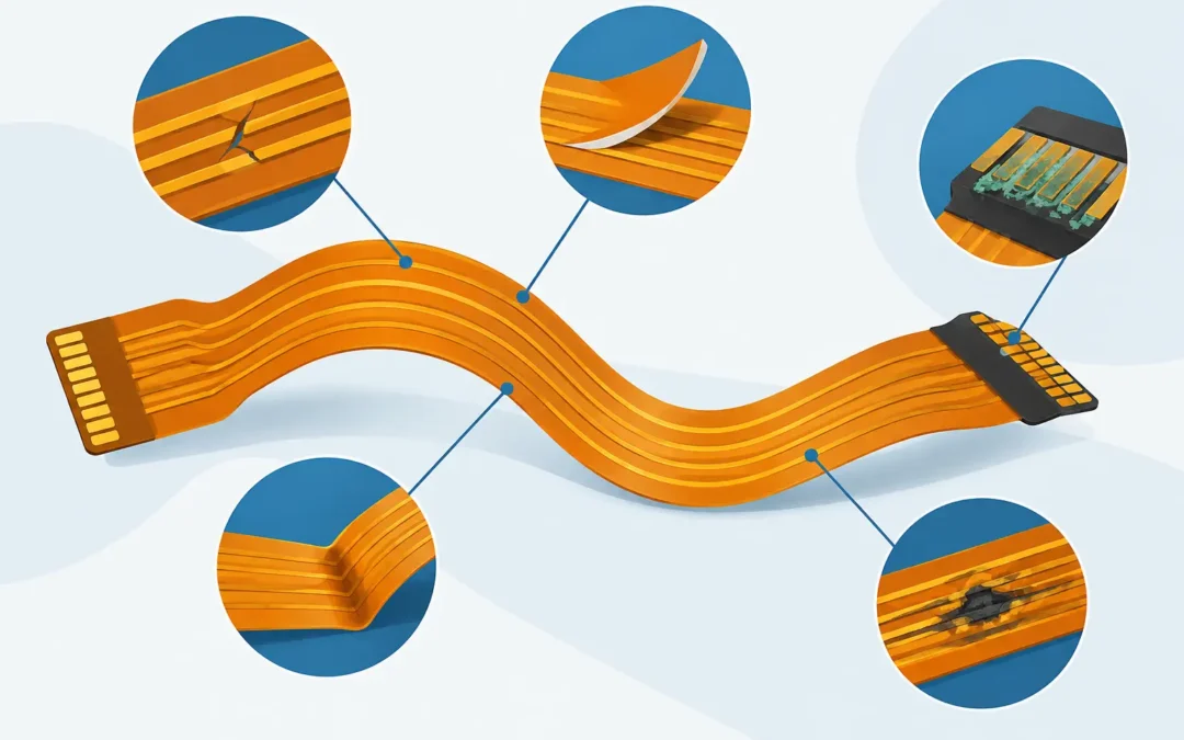
A flex circuit can pass electrical test at shipment and still fail months later at a bend point, solder joint, or connector interface. That gap between initial continuity and real service life is why common flex circuit failure modes must be evaluated at the design stage, not after a field return. The material stackup, bend geometry, copper profile, stiffener plan, assembly process, and operating environment all contribute to the final result.
For aerospace, defense, medical, automotive, and industrial programs, the question is not simply whether a flex circuit works. The question is whether it will continue to work through vibration, thermal cycling, repeated motion, installation handling, and the full intended service interval. Failure analysis is most effective when it connects the symptom to the design and manufacturing condition that created it.
Common Flex Circuit Failure Modes and Their Causes
Conductor fatigue at dynamic bend locations
Conductor fatigue is one of the most frequent flex-circuit failures in applications with repeated movement. It typically appears as an intermittent open that progresses to a permanent open, often near the edge of a bend, at a trace transition, or where the flex exits a stiffened area.
Repeated bending work-hardens copper. Once microcracks begin, resistance can rise under flexing before a static continuity test detects a complete break. Tight bend radii, excessive bend cycles, and copper features placed in the bend zone accelerate the process. Rolled-annealed copper is generally the preferred choice for dynamic applications because its grain structure is better suited to repeated flexing than electrodeposited copper. That choice alone, however, does not correct a poorly planned bend area.
Trace routing matters. Traces should cross a bend perpendicular to the bend axis where practical, be distributed rather than tightly grouped, and avoid sharp corners or abrupt width changes. Pads, vias, and plated through-holes should remain outside the active bend region. For a static installation bend, requirements can be less restrictive, but the radius still must account for total circuit thickness and installation stresses.
Cracked plated through-holes and vias
In double-sided, multilayer, and rigid-flex constructions, plated through-hole and via cracking can result from thermal expansion mismatch. Copper plating, polyimide dielectric, adhesive systems, FR-4 rigid sections, and component solder joints do not expand at identical rates. Thermal cycling places those interfaces under repeated strain.
Symptoms may include intermittent layer-to-layer opens, failures that occur only at temperature extremes, or solder joints that appear sound while electrical continuity is lost below the component. In rigid-flex circuits, the transition between rigid and flexible areas deserves particular attention. A poor transition design can concentrate stress at the first plated hole near the flex interface.
Prevention begins with stackup discipline. The plated-hole structure, dielectric thickness, copper weight, and rigid-to-flex transition must be engineered as a system. Controlled drilling, desmear, plating processes, and verification testing are equally important. For high-reliability builds, cross-section analysis provides useful evidence that plating distribution and layer registration meet the intended construction.
Coverlay, solder mask, and adhesive delamination
Delamination occurs when coverlay, adhesive, solder mask, or laminate separates from the copper or base material. It may present as lifting at pad edges, bubbling, exposed copper, or loss of insulation between conductors. In some cases, the condition appears only after reflow, environmental exposure, or thermal shock testing.
Moisture is a common contributor. Polyimide absorbs moisture, and rapid exposure to soldering temperatures can generate internal vapor pressure. Improper material storage, insufficient bake control when required, contamination, and incompatible assembly temperatures can all raise delamination risk. Excessive rework adds another source of heat exposure that may exceed the limits assumed during material selection.
The correct solution depends on the construction. Adhesiveless material may offer advantages in fine-line or high-temperature designs, while adhesive-based constructions remain appropriate for many cost-sensitive or established applications. The key is selecting materials based on the actual thermal profile, flex demand, and dielectric requirements rather than treating all polyimide flex as interchangeable.
Solder-joint cracking at stiffener and flex transitions
A component mounted on a flex circuit needs controlled support. Without it, the circuit can deflect during handling, mating, vibration, or service, placing strain directly into solder joints. Connectors are particularly vulnerable because insertion and extraction forces can be transferred into their terminations.
Stiffeners provide local rigidity, but they can also create a stress concentration when their edge is positioned too close to a component, pad, or bend zone. The result may be cracked solder fillets, lifted pads, or intermittent connector contacts. A stiffener should extend far enough to support the assembly area while allowing a managed transition to the flexible portion of the circuit.
Assembly process control is also central. Pad geometry, surface finish, solder paste deposition, component placement, and reflow profile must match the flex construction. A production partner with both circuit fabrication and in-house assembly capability can resolve these interfaces before they become a supplier handoff problem.
Pad lifting and conductor separation
Pad lifting is often associated with rework, but the root cause may begin earlier. Thin copper, inadequate pad support, excessive peel stress, improper rework temperature, or repeated thermal excursions can separate the copper feature from the base material. Fine-pitch component pads and connector pads require particular care because there is little margin for damage.
In flex, a pad that appears mechanically secure may still be exposed to peel forces if the circuit is folded, pulled, or bent near the termination. Stiffeners, strain-relief geometry, and adequate spacing between pads and bend areas reduce that risk. When repair is likely during prototype development, the design should account for a realistic rework window rather than assuming each pad will see only one assembly cycle.
Abrasion, tearing, and handling damage
Not every failure begins electrically. Flex circuits can be damaged during depanelization, shipping, installation, or service when edges rub against enclosures, sharp metal features, fasteners, or moving assemblies. A small nick along a circuit edge can propagate into a tear, especially where the flex is under tension.
Mechanical protection may include coverlay extensions, formed strain relief, controlled fold lines, carrier fixtures, or housing features that prevent rubbing. Tooling holes and handling tabs should be designed for the actual manufacturing and assembly sequence. A circuit that is easy to fabricate but difficult to install is not production-ready.
Corrosion and insulation degradation
Moisture, condensation, salt exposure, chemical residues, and electrical bias can cause corrosion or electrochemical migration. These mechanisms are especially relevant in automotive, outdoor industrial, marine-adjacent, and high-humidity applications. Failure may appear as increased leakage current, dendritic growth between conductors, or open circuits at exposed copper features.
Surface finish selection, coverlay coverage, cleanliness requirements, and enclosure design must work together. Fine trace-and-space geometries require closer attention because reduced spacing leaves less tolerance for contamination and moisture. If the unit will face harsh environments, the qualification plan should replicate those conditions rather than relying solely on room-temperature electrical test.
Diagnosing the Failure Without Guesswork
A failed flex circuit should be evaluated in its installed condition whenever possible. First determine whether the failure is static, temperature-dependent, vibration-dependent, or associated with motion. Intermittent defects frequently disappear once the assembly is removed from its fixture or allowed to return to room temperature.
Visual inspection can identify obvious cracking, lifted coverlay, abrasion, or solder damage. Continuity testing under controlled flexing can expose conductor fatigue. Cross-sections, X-ray inspection, microsection analysis, and thermal cycling may be warranted when the defect involves plated holes, internal layers, or solder interfaces. The right test method depends on the suspected mechanism, and forcing a destructive analysis too early can remove evidence.
Traceability is essential for recurring or mission-critical programs. Material lot data, fabrication travelers, assembly profiles, inspection records, and serialized test results help distinguish an isolated handling event from a process or design trend. This is particularly valuable when the same product is built across prototypes, low-rate initial production, and long-running production schedules.
Designing Out Failure Before Production
The most effective corrective action is usually taken before fabrication begins. Define whether each bend is static, limited-cycle, or dynamic. Identify bend zones on the drawing. Keep vias, pads, and abrupt copper geometry out of those zones. Specify the required service temperature, vibration exposure, chemical environment, and expected cycle count instead of leaving the manufacturer to infer them.
Manufacturing input should arrive early enough to affect the stackup and mechanical envelope. A design may be electrically correct yet difficult to laminate, plate, assemble, inspect, or test repeatably. GC Aero Flexible Circuits works through those production details with customers before they become schedule, yield, or reliability problems.
For a high-consequence application, prototype qualification should exercise the actual failure risks: motion where motion is expected, thermal cycling where temperature changes are expected, and assembly-level vibration where connectors and components carry mechanical loads. A flex circuit earns confidence by surviving its real operating conditions, not by looking acceptable on a bench test.
When a program identifies likely failure mechanisms early, the team can make deliberate trade-offs among thickness, bend life, density, cost, and assembly complexity. That is the point where a flex design becomes a dependable production component rather than a field-return waiting to happen.