
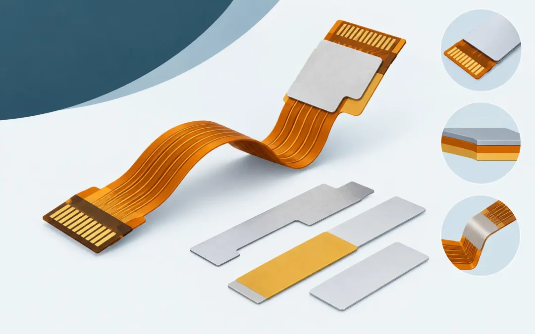
A flex circuit is designed to bend, but not every area of a flex assembly should remain flexible. Connector interfaces, component sites, test points, and handling zones often need localized support to survive assembly and perform reliably in service. This flex circuit stiffener guide explains how to define that support before fabrication, when changes are still practical and cost-effective.
A stiffener is not a substitute for sound flex-stackup design. It is a controlled mechanical feature that supports a specific function: creating a connector-ready tongue, limiting bend at a solder joint, providing a flat component-mounting area, or making an assembly easier to process. The correct material, thickness, adhesive system, and placement depend on the application and the assembly process.
What a Flex Circuit Stiffener Does
A stiffener is a bonded layer added to selected regions of a flexible printed circuit. It increases local rigidity without turning the full circuit into a rigid-flex construction. That distinction matters. A rigid-flex circuit uses rigid sections integrated into the multilayer stackup during fabrication; a stiffened flex circuit uses a separate reinforcement bonded after the flex circuit is built.
For many designs, the primary requirement is dimensional. A zero-insertion-force connector may require a specific tongue thickness so the contact force is correct. A surface-mount component area may need a stable, planar foundation through solder paste printing, pick-and-place, and reflow. In other cases, the stiffener reduces repeated flexing near a vulnerable transition.
The key word is localized. Extending a stiffener farther than necessary can shift stress to its edge, restrict a required fold, add mass, or complicate installation. The design should define exactly where rigidity starts and ends, based on the circuit’s actual mechanical use.
Flex Circuit Stiffener Guide: Start With Function
Stiffener selection should begin with the assembly requirement, not a default material callout. Ask what the reinforced area must accomplish and what it will experience during manufacturing and field use.
A connector tongue is usually controlled by finished thickness, insertion geometry, and wear requirements. A component area is controlled by planarity, thermal exposure, package size, and solder-joint reliability. A hand-contact or service area may be driven by handling durability. A bend-transition support may be driven by dynamic-cycle life and strain management.
These are different problems. A thick FR-4 stiffener can be appropriate beneath a dense component area yet be unsuitable at a thin connector interface. Polyimide may achieve a tight thickness requirement, but it does not provide the same rigidity as FR-4. Stainless steel provides exceptional thin-section support, but it changes weight, grounding considerations, edge finishing, and processing details.
Defining the function first gives the fabricator the information needed to recommend a manufacturable construction rather than simply building to an incomplete note.
Common Stiffener Materials and Their Trade-Offs
Polyimide Stiffeners
Polyimide is commonly used where a thin, flexible-compatible reinforcement is needed. It is well suited for ZIF connector fingers because it can be supplied in controlled thicknesses and maintains thermal stability through normal assembly processes. It is also useful when the stiffened region must retain some limited conformity rather than behave as a rigid panel.
The trade-off is stiffness. Polyimide adds support, but it will not produce the same flatness or mechanical resistance as FR-4 or metal. Adhesive thickness must also be included in the finished-thickness calculation. For connector applications, that total stackup should be specified and verified, not estimated from nominal film thickness alone.
FR-4 Stiffeners
FR-4 is a practical choice for component mounting, connector support, and handling areas that need substantial rigidity. It provides a stable platform for SMT or through-hole assembly and is available in a wide range of thicknesses. For assemblies with larger packages, repeated mating forces, or a need for operator handling, FR-4 is often the most economical solution.
Its limitation is bulk. FR-4 adds thickness quickly and can create an abrupt transition from stiff to flexible material. That transition should be kept outside the active bend area. If the circuit must fold close to the reinforcement, evaluate the bend radius and strain at the stiffener edge before releasing the design.
Stainless Steel Stiffeners
Stainless steel is used when high stiffness is required in a very thin profile. It can support compact assemblies where FR-4 thickness is not available, and it performs well in applications requiring dimensional stability. It may also be selected for mechanical durability in demanding industrial, aerospace, or medical equipment.
Metal introduces additional design considerations. It may require insulation from exposed conductors, special edge treatment, and a review of any electrical interaction with nearby circuitry. Its thermal behavior differs from the flex base material, which can affect flatness during reflow. It also generally adds cost and process complexity relative to polymer or FR-4 reinforcement.
Aluminum and Other Specialty Materials
Aluminum may be selected when low weight and heat spreading are priorities, while specialty composites can address unusual mechanical or thermal requirements. These are application-specific choices. They should be reviewed early with the fabricator because adhesive compatibility, machining, insulation, and assembly temperatures can determine whether the material is practical.
Thickness Is a Finished Stackup Requirement
One of the most common errors in stiffener documentation is calling out only the raw stiffener thickness. The assembly does not see the raw material. It sees the combined thickness of the flex circuit, bond adhesive, coverlay or solder mask features, and stiffener.
For a connector tongue, specify the required finished thickness and its allowable tolerance. Then identify the measurement region. A coverlay opening, copper feature, or plated finish can alter the local result enough to affect connector engagement. If a connector supplier provides a target thickness range, include that requirement directly in the fabrication data.
For component areas, thickness is often less about a connector tolerance and more about maintaining coplanarity during assembly. Here, the stackup should account for component mass, board support during reflow, fixture contact, and any mechanical fasteners. A local stiffener that is technically thick enough can still be inadequate if its footprint does not support the full load path.
Placement, Edge Location, and Bend Relief
A stiffener should not terminate in a high-flex region unless the design has been evaluated for that condition. The edge of the reinforcement changes the neutral axis and concentrates bending stress. If repeated motion is expected, place the stiffener edge away from the bend line and provide adequate distance for a gradual transition into the flexing area.
Copper routing matters as well. Avoid placing critical traces, vias, or pad-to-trace transitions where the stiffener edge will experience repeated bending. When possible, route conductors perpendicular to the bend only where necessary and use generous bend radii. Dynamic flex applications deserve a dedicated mechanical review because a construction acceptable for one-time installation may fail under thousands of cycles.
Stiffener geometry should also support manufacturing. Small isolated pieces, narrow tabs, sharp internal corners, and intricate outlines can increase handling difficulty and reduce bond consistency. A clean outline with practical tolerances helps maintain repeatability from prototype through production.
Adhesive and Assembly Process Must Be Considered Together
Most stiffeners are attached with pressure-sensitive or thermoset adhesive systems. The adhesive choice affects bond strength, thickness control, temperature capability, moisture resistance, and outgassing behavior. It must be compatible with the assembly sequence, especially if the circuit will pass through lead-free reflow, conformal coating, sterilization, or environmental testing.
Do not assume a stiffener can be added after components are installed. The order of operations depends on the geometry, access, thermal exposure, and equipment used. In many cases, applying the stiffener before SMT assembly provides better support and process control. In other cases, a post-assembly reinforcement may be necessary to avoid interference with placement or soldering.
For mission-critical hardware, define verification requirements as part of the build plan. Depending on the application, that may include thickness measurement, visual inspection for adhesive coverage and edge lift, dimensional inspection, bend testing, or sample thermal cycling. The right inspection method should prove the requirement that drove the stiffener design.
Documentation That Prevents Production Delays
A complete fabrication package should show the stiffener material, nominal thickness, adhesive requirement if specified, location, outline, side of the flex circuit, and finished-thickness requirement where applicable. It should also identify restricted areas, bend zones, connector interfaces, and any special inspection criteria.
If the stiffener is part of a connector system, include the connector manufacturer’s thickness and insertion requirements. If it supports components, identify the assembly side, package locations, and whether the area must remain flat during reflow. These details prevent a fabricator from having to infer critical mechanical intent from incomplete artwork.
GC Aero Flexible Circuits works with engineering teams to convert those requirements into production-ready flex and rigid-flex assemblies, including integrated component assembly when the program requires a single accountable manufacturing partner.
The best stiffener design is usually the one that solves one clearly defined mechanical problem with the least added complexity. Establish the functional requirement early, document the finished stackup rather than a nominal material alone, and review the transition between supported and flexing regions before committing the design to production.